Mechanical Drawing Symbols
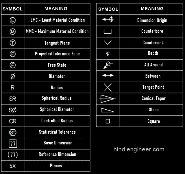
Mechanical Drawing Symbols - Web may 5, 2022 by brandon fowler. Web the following is a short list of symbols that normally appear on a technical drawing and need understanding. Web learn about the common mechanical drawing symbols and their meanings in various fields of mechanical engineering, such as bearings, dimensioning, fluid power, and. In the example shown, 24 is the nominal size. We will discuss this topic further. Web 83 rows graphical symbols for use on mechanical engineering and construction drawings, diagrams, plans, maps and in relevant technical product documentation Web engineering working drawing basics is a pdf document that introduces the fundamental principles and practices of engineering drawing. Symbols take less time to apply on a. Technical drawings, also called mechanical drawings,. Understanding how to read part drawings is essential to designing a product. Symbols take less time to apply on a. Understanding how to read part drawings is essential to designing a product. Web learn about the common mechanical drawing symbols and their meanings in various fields of mechanical engineering, such as bearings, dimensioning, fluid power, and. Lighter lines show connected pipe,. Symbols are shown in black lines. Web the following is a short list of symbols that normally appear on a technical drawing and need understanding. Understanding how to read part drawings is essential to designing a product. Here are more commonly used engineering drawing symbols and design elements as below. Note the comparison with the iso standards. We will discuss this topic further. Understanding how to read part drawings is essential to designing a product. These symbols can include lines, boxes, circles, arcs and text. Web what are the most commonly used engineering drawing symbols and their meanings? Web the following is a short list of symbols that normally appear on a technical drawing and need understanding. You can also check out the. Understanding how to read part drawings is essential to designing a product. Lighter lines show connected pipe,. It covers topics such as types of. Web 262 rows engineering drawing abbreviations and symbols are used to communicate. Technical drawings, also called mechanical drawings,. Web mechanical drawing symbols are used to represent components and processes in diagrams. Web 83 rows graphical symbols for use on mechanical engineering and construction drawings, diagrams, plans, maps and in relevant technical product documentation It covers topics such as types of. We offer you our tips which we believe are useful for dispelling. Web learn about the common mechanical. The table shows dimensioning symbols found on drawings. Web mechanical drawing symbols are used to represent components and processes in diagrams. Understanding how to read part drawings is essential to designing a product. Web what are the most commonly used engineering drawing symbols and their meanings? Web 1.1 symbols permit consistency in the way dimensions and tolerances are specified, and. We will discuss this topic further. These symbols can include lines, boxes, circles, arcs and text. Understanding how to read part drawings is essential to designing a product. Basic types of symbols used in engineering drawings are countersink, counterbore, spotface, depth, radius, and diameter. The table shows dimensioning symbols found on drawings. These symbols can include lines, boxes, circles, arcs and text. Most symbols have been in y14.5 since at least. Web learn about the common mechanical drawing symbols and their meanings in various fields of mechanical engineering, such as bearings, dimensioning, fluid power, and. Web what are the most commonly used engineering drawing symbols and their meanings? Understanding how to read. Web engineering working drawing basics is a pdf document that introduces the fundamental principles and practices of engineering drawing. Symbols take less time to apply on a. Web what are the most commonly used engineering drawing symbols and their meanings? It covers topics such as types of. It is the size that the tolerance. Basic types of symbols used in engineering drawings are countersink, counterbore, spotface, depth, radius, and diameter. We will discuss this topic further. Web 83 rows graphical symbols for use on mechanical engineering and construction drawings, diagrams, plans, maps and in relevant technical product documentation Lighter lines show connected pipe,. Note the comparison with the iso standards. Understanding how to read part drawings is essential to designing a product. Web may 5, 2022 by brandon fowler. Web 1.1 symbols permit consistency in the way dimensions and tolerances are specified, and each symbol has a clearly defined meaning. These symbols can include lines, boxes, circles, arcs and text. We offer you our tips which we believe are useful for dispelling. Web mechanical drawing symbols are used to represent components and processes in diagrams. It covers topics such as types of. Web learn the basics of reading engineering drawings, a graphical language that shows the information and requirements needed to manufacture an item or product. Basic types of symbols used in engineering drawings are countersink, counterbore, spotface, depth, radius, and diameter. The table shows dimensioning symbols found on drawings. You can also check out the gd&t symbols and terms on our site. Web 262 rows engineering drawing abbreviations and symbols are used to communicate. Technical drawings, also called mechanical drawings,. In the example shown, 24 is the nominal size. It is the size that the tolerance. We will discuss this topic further.
Mechanical Engineering Drawing Symbols Pdf Free Download at

Mechanical Engineering Drawing Symbols Pdf Free Download at GetDrawings

Mechanical Engineering Drawing Symbols Pdf Free Download at

Mechanical Engineering Symbols Cadbull

Mechanical Engineering Drawing Symbols Pdf Free Download at

Mechanical Drawing Symbols

Engineering Drawing Symbols And Their Meanings Pdf at PaintingValley
M&e Drawing Symbols Back To Basics Komseq
Mechanical Engineering Drawing Symbols Pdf Free Download at
Radius Symbol Drafting
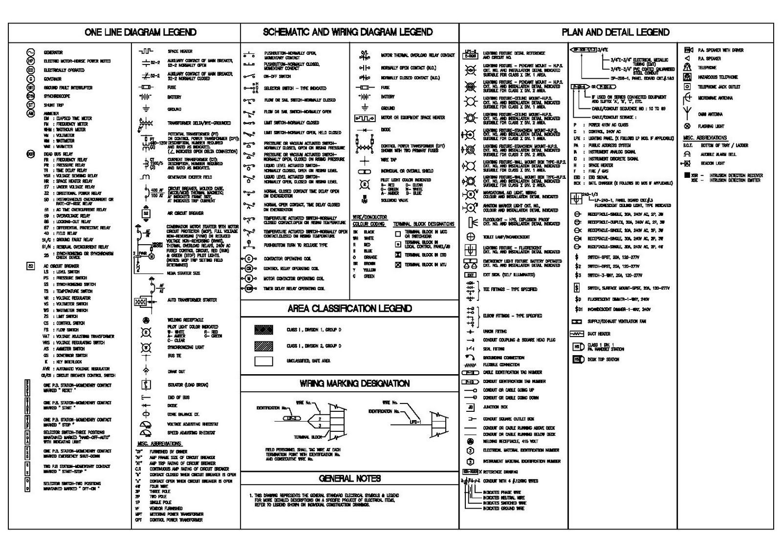
Web Learn About The Common Mechanical Drawing Symbols And Their Meanings In Various Fields Of Mechanical Engineering, Such As Bearings, Dimensioning, Fluid Power, And.
Lighter Lines Show Connected Pipe,.
Web What Are The Most Commonly Used Engineering Drawing Symbols And Their Meanings?
Web 83 Rows Graphical Symbols For Use On Mechanical Engineering And Construction Drawings, Diagrams, Plans, Maps And In Relevant Technical Product Documentation
Related Post:
