Isometric Piping Drawing Symbols
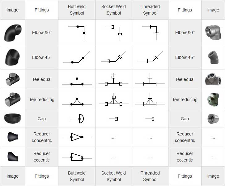
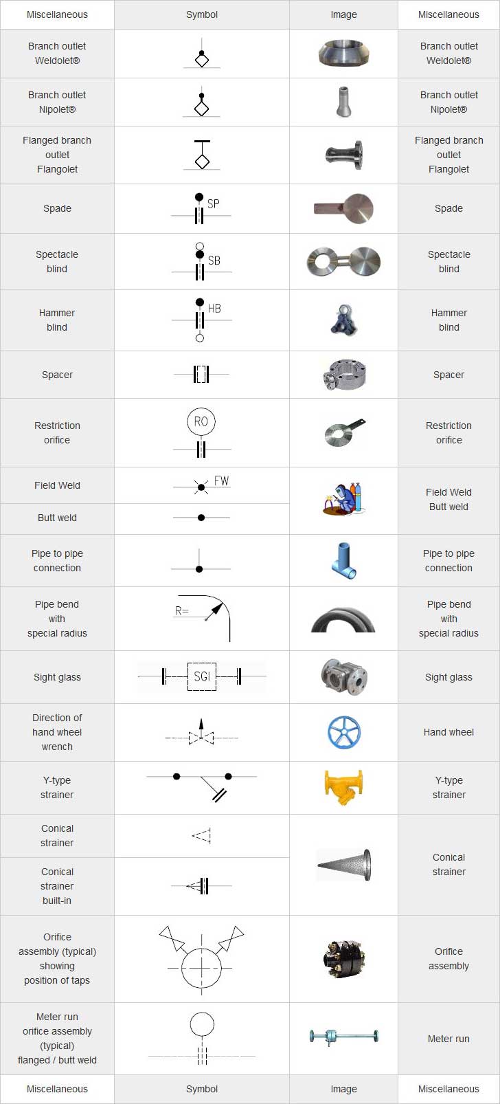
Isometric Piping Drawing Symbols - Lighter lines show connected pipe, and are not parts of the symbols. An inexpensive alternative to other software costing hundreds of dollars more. Web a piping isometric checklist is a list of checkpoints that are ensured while checking the piping isometric. Line numbers (nos.) line specifications; Web isometric symbols for piping fittings. All of our vector cad models are of the highest quality. Understanding the intricacies of pipeline isometric drawings, including iso standard isometric symbols, fittings, flanges, valves, and special components, is foundational for professionals in the. Isometric drawings are typically used to show the details of a piping system, such as the size and type of piping, the direction of flow of the fluids, and the location of valves, pumps, and other equipment nozzles. Web piping isometric dwg symbols designed just for you in autocad. In this dwg file you will find a huge collection of pipeline isometric drawings which are created in 2d format. Web drawing an isometric proportionally simply means drawing a 10m run of pipe twice as long as a 5m length of pipe. Lighter lines show connected pipe, and are not parts of the symbols. Web piping symbols for isometric drawings. Web the symbols that represent fittings, valves and flanges are modified to adapt to the isometric grid. Usually, piping isometrics. Web the symbols that represent fittings, valves and flanges are modified to adapt to the isometric grid. Web piping isometric drawing symbols for various markings. Construction techniques for isometric drawing. Web drawing an isometric proportionally simply means drawing a 10m run of pipe twice as long as a 5m length of pipe. Web piping symbols for isometric drawings. Automatically set the grid and snap with a click of the mouse. Web piping symbols for isometric drawings. Web importance of piping isometrics to the construction, commissioning, safe operation and maintenance of a process plant. All of our vector cad models are of the highest quality. Web a piping isometric checklist is a list of checkpoints that are ensured while. Web placement and notation of supports and hangers in the drawing. Isometric drawings employ specific symbols and notations to convey information efficiently. Are tagged with the same codes used on the p&id and ga. All symbols are drawn to work with a grid system. Usually, all these pipework the pipeline draw symbols are constant and do cannot varied tons from. How to read piping isometrics using real plant drawings. These drawings employ piping symbols and conventions to depict different components of the pipeline, making it easier for. Web with m4 drafting you can create piping isometric drawings manually using your own symbols. Works with inch or millimeter drawing units. It is quite easy creating isometric lines on isometric planes. For readers and understanding a piping isometric drawing, one should learn the piping isometric drawing symbols conclusive. With m4 plant you can design your pipelines directly in 3d and then create the corresponding piping isometric drawing s ready for production in seconds with just the push of a button. Piping iso symbols and meaning. Web with m4 drafting you can. Web piping isometric drawing is an isometric representation of single pipe line in a plant. Web isometric symbols for piping fittings. Web with m4 drafting you can create piping isometric drawings manually using your own symbols. Dimensions and location of instruments. Web what is an isometric drawing? This is done by drawing the lines parallel to isometric axes. Web drawing an isometric proportionally simply means drawing a 10m run of pipe twice as long as a 5m length of pipe. The iso, as isometric are commonly referred, is oriented on the grid relative to the north arrow found on plan drawings. Web isometric drawings excel at visually. They are not realistic, pipes are shown as single lines, and symbols are used to represent pipe fittings, valves, pipe gradients, welds, etc. Various symbols are used to indicate piping components, instrumentation, equipments in engineering drawings such as piping and instrumentation diagram (p&id), isometric drawings, plot plan, equipment layout, welding drawings etc. Are tagged with the same codes used on. An inexpensive alternative to other software costing hundreds of dollars more. Usually, all these pipework the pipeline draw symbols are constant and do cannot varied tons from one organization the another. Knowing aforementioned piping drawing symbols will provide. Web the symbols that represent fittings, valves and flanges are modified to adapt to the isometric grid. They are not realistic, pipes. Web the process of drafting isometric drawings for a pipeline system involves referencing the arrangements of the pipelines, sections, and elevation drawings during its development. This is done by drawing the lines parallel to isometric axes. Web what is an isometric drawing? Web piping symbols for isometric drawings. All of our vector cad models are of the highest quality. Knowing aforementioned piping drawing symbols will provide. Works with inch or millimeter drawing units. How to read piping isometrics using real plant drawings. Line numbers (nos.) line specifications; Construction techniques for isometric drawing. Automatically set the grid and snap with a click of the mouse. Checkout list of such symbols given below. Usually, all these pipework the pipeline draw symbols are constant and do cannot varied tons from one organization the another. Isometric drawings are typically used to show the details of a piping system, such as the size and type of piping, the direction of flow of the fluids, and the location of valves, pumps, and other equipment nozzles. Piping isometric drawing consists of three sections. These drawings employ piping symbols and conventions to depict different components of the pipeline, making it easier for.
Basic Piping Isometric Symbols Piping Analysis YouTube

What is Piping Isometric drawing? How to Read Piping Drawing? ALL

Piping Isometric Drawings The Piping Engineering World
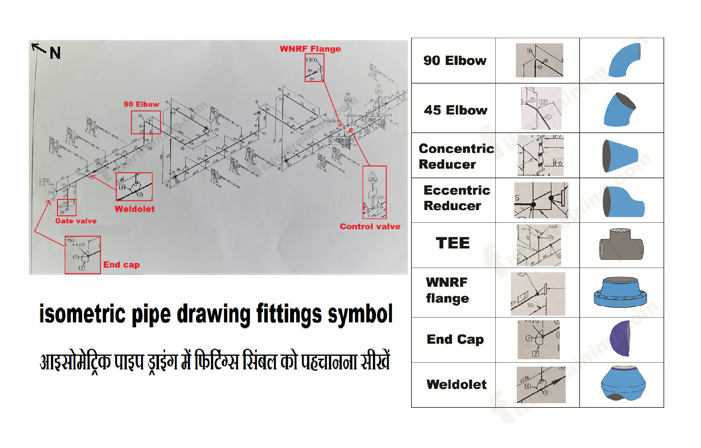
isometric pipe drawing fittings symbol Fitter training
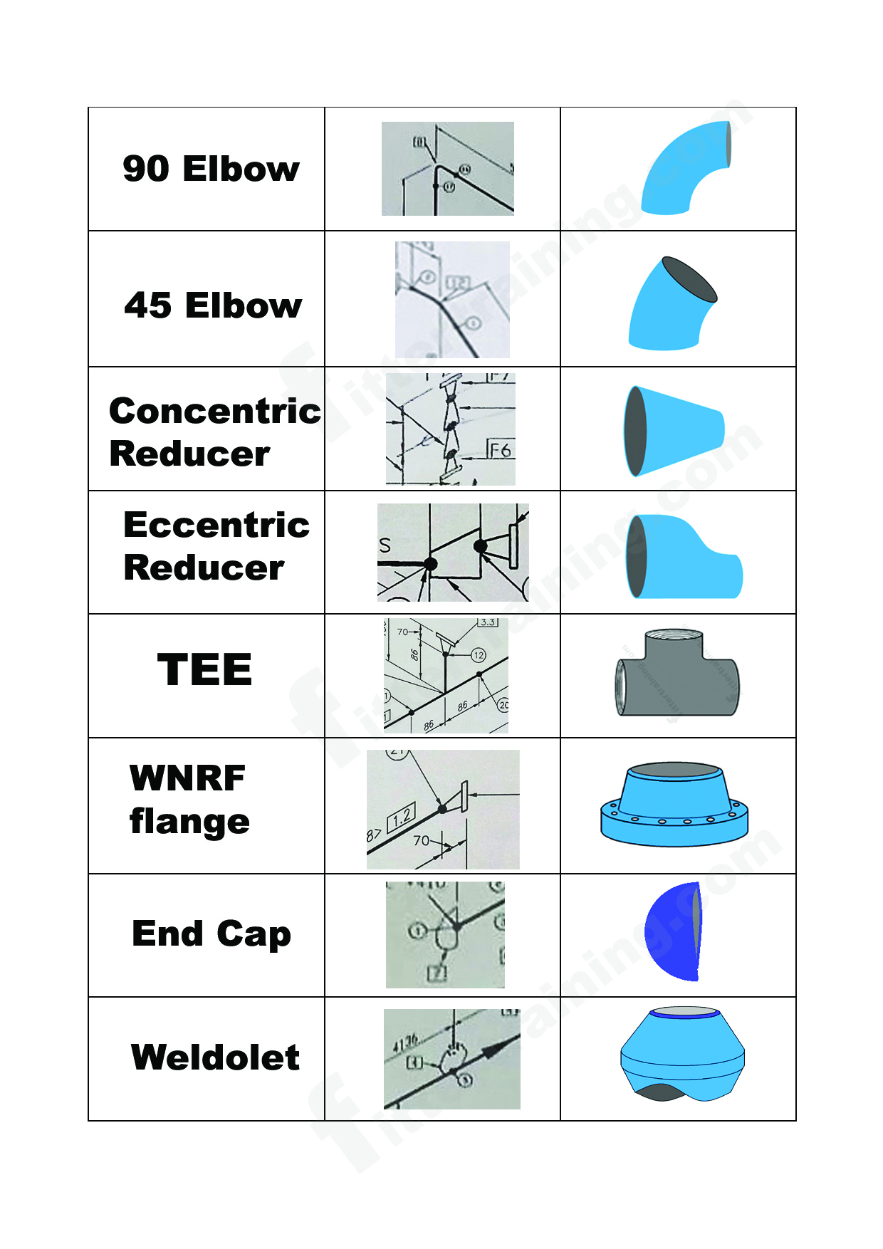
isometric pipe drawing fittings symbol Fitter training

Piping Isometric DWG Symbols Free Download Drawing in CAD

How to read isometric drawing piping dadver

Piping Isometric Drawing Symbols Pdf at Explore
Piping Coordination System Mechanical symbols for Isometric drawings
Piping Coordination System Mechanical symbols for Isometric drawings
Isometric Drawings Employ Specific Symbols And Notations To Convey Information Efficiently.
An Inexpensive Alternative To Other Software Costing Hundreds Of Dollars More.
All Symbols Are Drawn To Work With A Grid System.
Web Piping Isometric Drawing Symbols For Various Markings.
Related Post: